- Visibility 214 Views
- Downloads 48 Downloads
- DOI 10.18231/j.idjsr.2022.016
-
CrossMark
- Citation
Introduction
Patients with protrusion or crowding typically require extraction procedures. Once extraction is chosen, the incisor's anterior-posterior position should be defined, and the force system should be determined. There are three categories of mechanics for differential space closure: Group A, Group B, and Group C. The mechanics of groups A and C are more difficult than those of group B. 1 Friction/sliding and frictionless/loop mechanics are the two fundamental categories of space closure mechanics. Since there is no guiding wire and no specific friction, The spring offers the necessary M/F ratio in three dimensions and is more adaptable and predictable because there is no force loss from friction.[1]
Similar to sliding, loop mechanics also comprises three steps during space closure: tipping, translation, and root movement. A correctly constructed appliance differs in that it has a wider activation range and more constant force, moment, and M/F ratio, which results in a constant centre of rotation.[1] We have discussed the numerous loops used frequently in orthodontics in this review paper, including ideal dimension, activation, and investigations using space closure by loops.
Components of a loop
Loops consists of horizontal force system, vertical force system, alpha bend, beta bend and helical component. Each loop is constructed with one or more of the above components. Specific component of each loop has been mentioned under the respective loop. [2]
Classification of loops
Based on configuration
Horizontal loops(e.g. boot loop)
Vertical loops
Combination(T Loop)
Based on purpose of the loop
Leveling and Aligning
Retractione
Multipurpose
Based on presence of helix
Loops without helix(e.g. vertical loop)
Loops with helix(e.g. Helical bulbous loop)
Based on function
Opening loops
Closing loops
General Concepts of Frictionless Mechanics
Following is a discussion of frictionless mechanics' fundamental ideas:
In frictionless mechanics, the brackets do not slide along the archwire as the teeth are moved. Loops or springs are used to retract anything.
A retraction spring's force is generated by drawing its distal end through the molar tube and then cinching it back.
The wire configuration and the presence of pre-activation or gable bends, which cause an activation moment, define the moment.
In general, the activation moment is more favourable and the overall M/F ratio is better the closer the wire is to the bracket.
Biomechanical Properties of Loops
An efficient loop has a wide action range, a high working load limit, and a low load deflection rate.[2], [3] The height of the loop can be increased, there can be an additional wire at the loop's apex, and the loop can be angled from base to apex to improve M/F ratio, among other parameters. The moments produced at the alpha and beta ends are significantly altered by the loop's positioning being off-center. Alpha moment would raise and beta moment would decrease as the loop was positioned towards to the anterior side. The management of anchorages can benefit greatly from differences in M/F ratios. As a result, a larger beta moment causes the posterior anchoring to be enhanced. Interbracket distance is a crucial factor in determining the biomechanical characteristics of a loop because when it is smaller, off-centering has a more substantial impact on the moment.[4]
Vertical loop- Robert strang ([Figure 1])
It is made out of 0.016" SS wire, and it is 6mm by height. Vertical loops can be used to open or close spaces and rotate teeth. They can also be closing loops or opening loops.[1] Burstone discussed the vertical loop's force system in terms of retraction mechanics. A typical clinical application generates a force deflection rate of 437g/mm and a moment to force ratio of 2.2mm at a vertical height of 6mm. For uncontrolled tipping, a moment to force ratio of 2.2mm is insufficient. The height of the loop can be increased to increase the moment to force ratio. This height can be increased by adding a helix, although helixes with more than three turns are ineffective. As the helix is positioned more apically, the M/F ratio rises linearly, further lowering force deflection rate. In Beggs mechanotherapy, archwires with vertical loops are used to align the anterior teeth. The loops make the wire stretch wider between the teeth and result in softer pressure when the object is moved. A circular cuspid hook that lies on either side of the mesial aspect of the cuspid bracket is used to create the looped arch. In order to create overcorrection of rotations, labio-lingual movement, or mesio-distal movement, the loops are then activated.
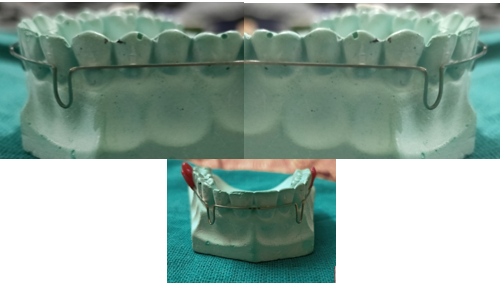
Horizontal loop / Boot loop- Morris M. Stoner in 1960 ([Figure 2])
It is formed by placing the active legs parallel to the arch wire. Incorporating a horizontal loop allows greater control over the direction of the force.[5] A horizontal loop provides for more precise control over the force's direction.[5] The main benefit of the horizontal loop is the decrease in vertical plane or occluso-gingival force, which enables fast bracket engagement in severely positioned teeth that the operator may desire to elevate or depress.
It works well for opening bites. On extremely packed teeth, immediate bracket engagement is feasible without using excessive force. The horizontal loop can be shaped to press against the gingival area and create a torquing activity on the root, however this has not been found to be very effective in clinical trials. The double Horizontal Loop performs best when it is kept on a single tooth either above or below the line of occlusion.[5]

Asymmetric T loop- James hilger in 1992 ([Figure 4])
This loop enables bite opening and space closure at the same time. It is constructed using TMA wire that is either 0.016" X 0.022" or 0.019" X 0.025" with a 5mm vertical step, a 2mm anterior loop, a 5mm posterior loop, and an accentuated reverse Spee curve.[6] Short mesial loop compression and extended distal loop opening are used to activate the asymmetric T loop.
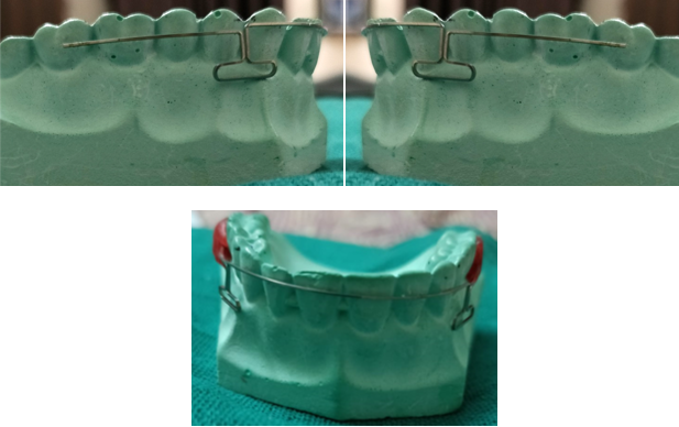
Opus loop-raymond E. siatkowski in 1977(Fig5)
In the study, closing loop design for usage in continuous arch wires was approached methodically. The moment-to-force ratio (M/F) equations are derived during the design phase using Castigliano's theorem in terms of loop geometry.[2]
The ascending legs are at an angle of 70 degrees to the plane of the brackets, and the apical horizontal leg is 10mm long. The ascending legs, especially the apical loop legs, must be spaced apart by no more than 1 mm. Opus loop has the ability to deliver M/F between 8.0 and 9.1 mm. Dimensions: 0.5 mm radius, 10 mm radius, and 10 mm height. It is made of 0.016 to 0.022 inch stainless steel wire, 0.018 to 0.025 inch stainless steel wire, or 0.017 to 0.025 inch TMA wire. Opus 90 and Opus 70 are two variations on the Opus loop.
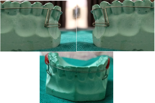
PG retraction spring- poul Gjessing in 1985 ([Figure 6])
The final spring design was created using 0.016 x 0.022 inch stainless steel wire and was refined utilising a step-by-step process on a bench testing setup. The ovoid double helix loop that extends 10 mm apically is the main active component. Instead of correcting rotations and/or excessive deviations in inclination of the canine, the spring is designed to resist rotational and tipping tendencies during retraction. Therefore, it is required to stop levelling the buccal segments before inserting the spring. Pulling away from the molar tube until the two halves of the double helix are separated by 1 mm results in activation to 140 to 160 gms. This process is repeated every 4 weeks. After retraction, lingual elastics can be used to readily correct any minor canine rotations that may have occurred due to anatomical variations in the root structure.[3]
For the anterior section, the moment-to-force ratio is significant, ranging from 7 mm to 10.5 mm at 3 mm and 1 mm activation, respectively. These numbers aren't as high as what Gjessing stated.[5]
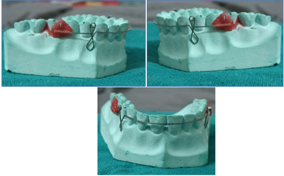
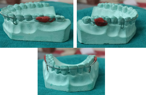
Tear drop loop - by R. G. alexander ([Figure 7])
Mandibular incisor movement requires an optimal force of about 2.60 N to be delivered. The teardrop springs of 6 mm height activated by 0.5 mm, which gave 2.51 N force, and the teardrop loop of 8 mm height activated by 1.0 mm, which provided 2.77 N force, were the springs that came closest to this value. The values of the teardrop loops were less than 2.60 N for heights of 7 mm, less than 1.89 N for heights of 8 mm, and less than 1.37 N for heights of 0.5 mm when activated. The forces applied to the 7 and 8 mm high teardrop loops when they were activated by 1.5, 2.0, and 3.0 mm were greater than the optimal values for mandibular incisor movement.
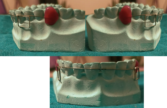
Box Loop - A. sivakumar in 2006 ([Figure 8])
The clinician can assess the moment-to-force ratio applied to the active unit. The point of force application in reference to the horizontal dimension of the "box" determines the direction of moments created at the loop. Any force and moment ratio— force, pure moment, or any other combination—can be released at the anterior bracket by activating the rectangular loop. By selecting various force application sites, adjusting the horizontal dimension of the loop, or angling the horizontal branch of the loop in relation to the bracket of the active unit, it is possible to get the required combination of moments and forces. Low load deflection rate is present.
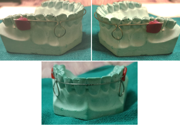
Omega Loop- Morris M. Stoner in 1960 ([Figure 9])
Morris M. Stoner published a description of an alternative to the open vertical loop in 1960. Due to its likeness to the Greek letter omega, after which it is named, it was given that name. Its advantage over an open vertical loop is that it is less likely to fracture due to a more even stress distribution along the loop's curvature as opposed to a concentration at the apex. It is frequently employed as a molar stop and for the physical movement of the root.[5] Gandhi et al. explained how to use a modified omega loop to close a maxillary midline diastema by inserting two crimpable hooks on the loop's arms that are orthogonal to one another. The closing force came from an E-chain stretched between the hooks provided the activating force to close the midline diastema.[7], [8]
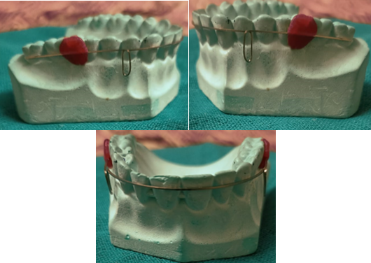
Reverse vertical loop- Dr. R. H. Strang in 1933 ([Figure 10])
The Bauschinger effect states that a closed loop has a wider range of activation than an open loop. Its activation range is quite constrained, and it also produces an M/F ratio that is far from optimal if controlled tipping or translation is desired. These are its two main drawbacks. In Beggs mechanotherapy, archwires with vertical loops are used to align the anterior teeth. The loops make the wire spread wider between the teeth and result in softer pressure when the object is moved. A circular cuspid hook that lies on either side of the mesial aspect of the cuspid bracket is used to create the looped arch. In order to create overcorrection of rotations, labio-lingual movement, or mesio-distal movement, the loops are then activated.
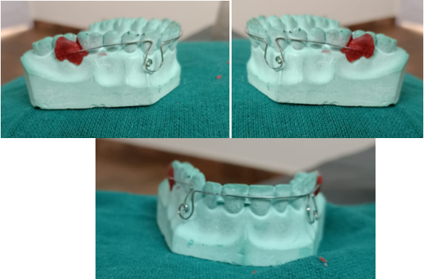
Snail loop -Dr. Pavan kumar vibhute in 2004 ([Figure 11])
Snail loop is spiral shaped and designed for en masse space closure of the anterior teeth. The snail loop is fashioned from 0.017"x0.025" stainless steel wire by bending a simple omega loop into a spiral shape, which provides the forces and moments. The outer portion of the snail loop is 8mm high and 6mm wide and the inner portion is 6mm high and 3mm wide. The snail loop has the potential for twice as much activation as a stainless steel omega loop before undergoing permanent deformation. The outer portion of the snail loop is 8mm high and 6mm wide, and the inner portion is 6mm high and 3mm wide
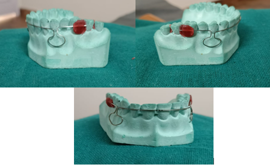
Mushroom Loop - Drs. Flavio uribe and eavindra nanda in 2003 ([Figure 11])
The moment to force ratio produced by this looping arch-wire is optimal for translation. Additionally, the loop does not interfere with the gingival tissue and does not easily distort, which improves the delivery of the orthodontic load. 0.017" x 0.025" β-III At distances that have been standardised between 26 and 46 mm with a 2 mm increment, Connecticut new arch-wire is utilised. The distances between the lateral incisors' distal surfaces are measured in millimetres. Pre-activation of the 3mm leg separation and any necessary anchorage reinforcement are done anteriorly. Reactivation of the loop is delayed until a space closure of 3 mm, ensuring that the moment to force ratio remains constant.[9]
Discussion
Smith and Storeyl suggest a force of 150 to 200 gm as being optimum for translation of human lower canines. Reitan advocates 250 gm and Lee recommends 150 to 260 gm , whereas Ricketts and associates prescribe 75 gm. Roth in his 'continuous arch' technique applied 170 to 215 gm force with 'Asher' type o f anterior headgear for enmasse retraction of anterior teeth. Ricketts on basis of study by Brian lee deemed 100 gm of force per cm of the root surface to be sufficient for bio progressive treatment. The total enhanced surface of the root is 1.65 cm 2 during the anteroposterior movement of maxillary canines and incisors. According to Ricketts, the force suggested for such root surface should be 165gm. Guray and Orhan successfully demonstrated that optimal force necessary for retraction of maxillary anterior sent averages 130 gm. Bennett and McLaughlin found 200 gm of elastic force sufficient for retraction of anterior segment in their 'preadjusted system'. To achieve translation of group of anterior w e assumed that the appropriate moment to force ratio (NVF) 8 to 9 .1 mm was necessary. The increase of wire length while maintaining the wire size decreases the load-deflection rate. And also the distribution of the wire in relation to the bracket determines the moment-to-force ratio.
In Friction mechanics the tooth is retracted or slides through the arch wire. It is used for both individual canine and enmasse retraction. Friction is present due to surface irregularities of arch wire and bracket
Following are its disadvantages: It gives variable force. E-chain absorbs water and saliva when exposed to oral environment causing degradation of force by 50%-70% by 1st day. Excess Stretching causes breakdown of internal bond leading permanent deformation. Dependent on patient cooperation in case of elastic bands. Due to friction and binding between bracket and arch wire applied force should be higher than the required optimum force because of decay in force. Mesial out movement of canine is seen. In frictionless mechanics the teeth are moved without the brackets sliding along the archwire. The force of a retraction spring is applied by pulling the distal end through the molar tube and cinching back.The moment is determined by the wire configuration and by the presence of pre-activation or of gable bends, which produce an activation moment.
Following are its advantage: control over the anterior and posterior anchoring with precision. Only the limit of the loop's activation will cause the tooth to move. It is feasible for teeth to move differently. Friction does not allow for as regulated of tooth movement as retraction loops or springs provide. stability of force.
Following are its disadvantage: When using retraction loops or springs, a solid grasp of mechanics is essential because even a small mechanical inaccuracy can produce massive faults in tooth movement. Compared to sliding mechanics, more chair time and wire-bending expertise are needed. Some patients may experience discomfort from the retraction loop, particularly those with shallow vestibules. maintaining good oral hygiene is difficult.
Conclusion
Friction and frictionless mechanics have their own merits and demerits. There is no such thing as the best method of space closure. Some situations will require some techniques over the others. The selection of any treatment, whether a technique, stage, spring or appliance design should always be based on the desired tooth movement. Thus orthodontic space closure should be an individually tailored procedure based on the diagnosis and treatment plan.
Goals to be considered for any universal method of space closure include:
Differential space closure: The capability of anterior retraction, posterior protraction or a combination of both should be possible.
Minimum patient cooperation: This is achieved by eliminating the usage of head gears and elastics.
Axial inclination control
Control of rotations and arch width
Optimum biologic response Tissue damage, particularly root resorption, should also be at a minimum
Operative convenience: The mechanism should be relatively simple to use, requiring only a few adjustments for the complication of space closure.
Source of Funding
None.
Conflict of Interest
None.
References
- C J Burstone, K Choy. The biomechanical foundation of clinical orthodontics. 2015. [Google Scholar]
- V P Jayade, CV Jayade. Essentials of orthodontic biomechanics-basic and applied.. 2011. [Google Scholar]
- R Gjessing. Biomechanical design and clinical evaluation of a new canine-retraction spring. Am J Orthod 1985. [Google Scholar]
- A J Kuhlberg, CJ Burstone. T-loop position and anchorage control. Am J Orthod 1997. [Google Scholar]
- RHW Strang. A Text-Rook of Orthodontia.. 1943. [Google Scholar]
- J J Hilger, P Farzin-Nia. Adjuncts to bioprogressive therapy- The asymmetrical T archwire. J Clin Orthod 1992. [Google Scholar]
- D J Halazonetis. Design and test orthodontic loops using your computer. Am J Orthod Dentofac Orthop 1997. [Google Scholar]
- M Gandhi, R Hattarki, KM Keluskar. Closure of a maxillary midline diastema using a modified omega loop. J Indian Orthod Soc 2015. [Google Scholar]
- F Uribe, R Nanda. Treatment of Class II, Division 2 malocclusion in adults: biomechanical considerations. J Clin Orthod 2003. [Google Scholar]
- Introduction
- General Concepts of Frictionless Mechanics
- Biomechanical Properties of Loops
- Vertical loop- Robert strang ([Figure 1])
- Horizontal loop / Boot loop- Morris M. Stoner in 1960 ([Figure 2])
- Asymmetric T loop- James hilger in 1992 ([Figure 4])
- Opus loop-raymond E. siatkowski in 1977(Fig5)
- PG retraction spring- poul Gjessing in 1985 ([Figure 6])
- Tear drop loop - by R. G. alexander ([Figure 7])
- Box Loop - A. sivakumar in 2006 ([Figure 8])
- Omega Loop- Morris M. Stoner in 1960 ([Figure 9])
- Reverse vertical loop- Dr. R. H. Strang in 1933 ([Figure 10])
- Snail loop -Dr. Pavan kumar vibhute in 2004 ([Figure 11])
- Mushroom Loop - Drs. Flavio uribe and eavindra nanda in 2003 ([Figure 11])
- Discussion
- Conclusion
- Goals to be considered for any universal method of space closure include:
- Source of Funding
- Conflict of Interest
